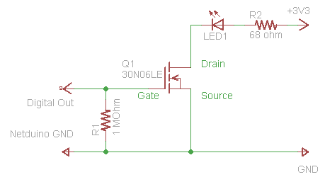
In “Exploring the Netduino #2: (Indirectly) Driving an LED“, we covered the electronic theory of how to use a Power MOSFET to turn the LED On and Off via a digital signal. In this post, we are going to walk the reader step-by-step on how to wire-up the circuit on a breadboard. If you’re using an Arduino, the steps are exactly the same.
As mentioned previously, you will need the following equipment and parts:
- An electronic breadboard
- A few common LEDs (like 5mm Red)
- A couple resistors (a 1 MOhm and a 68 or 100 ohm)
- N-Channel MOSFET (like RFP30N06LE)
- A 3.3v power supply or a 2-cell AA Alkaline battery pack (3v)
- Some jumper wires to connect the circuit together
- Multi-meter (optional)
- And a Netduino or Arduino, of course!
Understanding the Breadboard
The Bread board is an electronic designer’s tool for easily prototyping a circuit as it allows easy insertion and removal of wires and components. Yet there is enough friction in each individual socket to hold onto each component reasonably well. The bread board shown below is a pretty common variety.
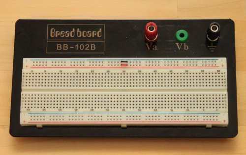 If you have never used a bread board before, let us quickly explain how it works.
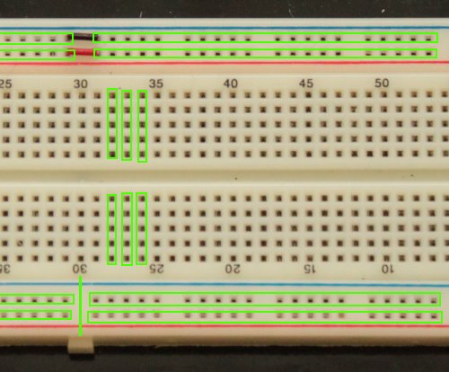 The bread board is broken up into positive (+) and negative (-) “power rails” (both top and bottom) which span the width of the board. The positive rails are colored in Red, while the negative rails are colored in Blue. It should be noted that the rails are intentionally broken in the middle around column 30. As shown in the picture above, red and black jumper wires connect the two upper rails together. The lower rails shown here are not jumped, so they remain separate.
In the middle of the bread board are multiple groups of holes organized in vertical columns and numbered every 5 (for reference). Each group consists of 5 pin sockets wired together vertically. These groups are not connected over the middle horizontal break of the board, nor do they connect horizontally.
Wiring up the Schematic
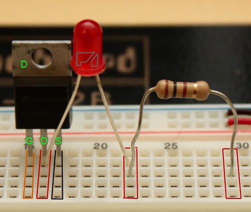
Looking at the circuit schematic, we are going to start with the right half of the circuit diagram which consists of the MOSFET, the LED, and the 68 ohm resistor. (The resistor shown in the image below is actually a 100 ohm resistor. The value is close enough to 68 ohms that the LED will still glow.)
1) Insert the MOSFET into the bread board such that each pin sits in its own vertical column of pin holes. (shown here in orange, red, and black)
2) Connect the Cathode (-) of the LED to the Drain on the MOSFET (shown in red labeled “D”). You can determine which side of the LED is the Cathode a few different ways:
- Identify the shortest leg.
- Locate the flat edge on the bevel at the base of the LED.
- Inside the LED are two small metal structures, find the large triangular one.
(see the image above.)
All of these methods will locate the cathode (the negative terminal) on the LED.
3) Connect the Anode (+) of the LED to its own column of holes. (shown as column 22 in the picture.)
4) Connect one side of the 68 (or 100) ohm resistor to the Anode of the LED, (shown as column 22) and connect the other side of the resistor to another independent column of holes. (shown as column 29 in the picture.)
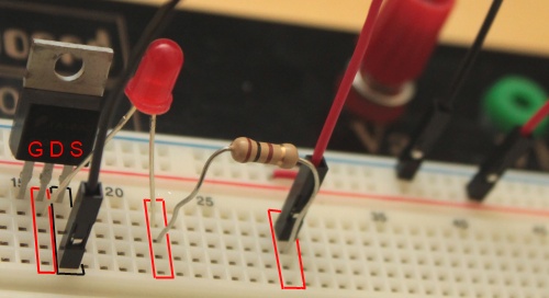 5) Wire the circuit up to the power rails by taking a red jumper wire and connect it from the resistor to the red power rail. Then take a black jumper wire and connect it from the Source of the MOSFET back to the blue power rail. (shown above.)
Looking up at the circuit diagram again, we are next going to wire up the left half of the schematic which consists of the MOSFET, the resistor, and the Netduino (or Arduino.)
6) Take the 1 mega ohm resistor and connect up one side to the Gate on the MOSFET and connect the other side of the resistor up to its own column. (shown in yellow and green.)
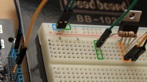 7) Connect a yellow jumper wire from the Gate to Digital Out 10.
(shown here in yellow.)
8} Connect a green jumper wire from the resistor to the Negative rail.
(aka. the “GND” rail — shown here in green.)
9) Connect a blue jumper wire from the Negative rail to Netduino GND.
(shown here in blue.)
10) Lastly, wire up your power supply to the terminals on the bread board and run jumper wires to the power rails. As shown here, the red battery pack wire leads to the red terminal which is jumpered by a red wire to the red power rail. Similarly, black to black to black to blue.
 When you have finished, your breadboard setup should look something like this.
Testing your setup
Now that you have wired up your circuit, it is time to test it without the Netduino to make sure the MOSFET can properly switch on the LED circuit.
- Disconnect the yellow wire from the Netduino.
- Leave the other side of the yellow wire connected to your gate.
- Attach the free side of the yellow wire to the red Positive (+) rail.
- The LED should light up.
- Disconnect the yellow wire from the positive rail and the LED should go out.
If you disconnect one end of the green wire and then briefly touch the free end of the yellow wire to the red positive rail, the LED should go on, but not turn off. As we explained previously, this is because there is no route to ground for the tiny capacitance in the gate. By reconnecting the gate to the ground (through the green wire), the LED should turn off again.
Next Time: Make LEDs *really* Glow (or: Fun with PWM)


7 replies on “Exploring the Netduino #3: Building the Circuit on a Breadboard”
[…] Pretzel Logix Logic so crazy, your head might explode. Skip to content HomeAbout ← Exploring the Netduino #1: Takin’ her for a Test Drive Exploring the Netduino #3: Building the Circuit on a Breadboard → […]
Thank you very much for the tutorial!
You’re welcome. It’s a bit of a “work-in-progress” as I intend to keep adding to it and revising it (as needed), but I hope other people find it helpful. 🙂
[…] Pretzel Logix Logic so crazy, your head might explode. Skip to content HomeAbout ← Exploring the Netduino #3: Building the Circuit on a Breadboard […]
I really like the arduino proto-shields for doing small breadboard projects. I have access to all my Netduino pins, and power/gnd!
[…] ← Previous […]
[…] ← Previous Next → […]