In “Exploring the Netduino #1“, you may recall that it was suggested that the reader take a look at the Netduino “Getting Starting” guide found on the Netduino.com site to get a feel for the hardware. The guide walks the user through a “Hello, World” equivalent where the user ends up getting the blue on-board LED to blink on and off. This tutorial aims to pickup where that guide left off.
Over the next few posts, we will cover how to wire up an LED to control its brightness using the Netduino’s Pulse-Width Modulation (PWM) features and supporting electronic circuitry.
To follow along, you will need the following:
- An electronic breadboard
- A few common LEDs (like 5mm Red)
- A couple resistors (a 1 MOhm and a 68 or 100 ohm)
- N-Channel MOSFET (like RFP30N06LE)
- A 3.3v power supply or a 2-cell AA Alkaline battery pack (3v)
- Some jumper wires to connect the circuit together
- Multi-meter (optional)
- And a Netduino, of course!
(Indirectly) Driving an LED with a Netduino Digital Output
In the post, “Exploring the Netduino #0“, it was mentioned that the Digital Out pins on the Netduino that support Pulse Width Modulation (PWM) can *safely* output up to 16mA. This is not really enough current to drive the common 5mm LED much less a whole string of LEDs. So if you are tempted to stick the LED’s Anode and Cathode pins directly into the Digital Out and the Ground (respectively), well here is some free advice:
Don’t! You’ll risk burning out your Netduino!!!
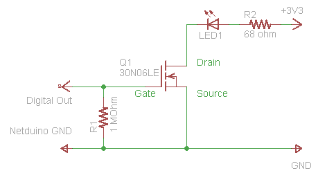
Instead, we are going to use a type of Transistor known as the “N-Channel MOSFET” to do the power switching for us. The MOSFET shown here is a very common model: RFP30N06LE — It can switch up to 60V and 30A (if heatsinked properly) the gate can turn on fully at a mere 2 volts. The best part? It can be had for less than $1 USD.
If you are not well skilled in electronics, do not worry: The circuit above is a very simple.
First, look at the component in the center of the diagram labeled Q1 — 30N06LE. That’s the MOSFET. It has 3 parts: a gate, a drain, and a source.
When a positive voltage above 2 volts is applied to the Gate, it turns ON. This allows current to flow between the Drain and the Source, just like a faucet allows water to flow out of a tap.
Next look at the whole circuit. It can be viewed easily in two halves:
- On the right side, the positive lead [+] of a 3.3 volt power supply (or 2 AA Alkaline batteries wired in series) is connected to a 68 ohm resistor and then the LED which leads to the “drain” pin on the MOSFET. From there, the MOSFET’s “source” pin leads back the ground/negative terminal [-] on the 3.3v power supply (or your 2-cell AA battery pack) to complete the circuit.
- On the left side, the Digital Out from the Netduino leads directly to the “gate” on the MOSFET. Leading away from the gate is a very high ohm resistor (1 mega ohm) connecting back to the Netduino’s Ground.
How does this work? Well, if you were to wire this up as it is, nothing would happen. This is because the gate has zero (0) voltage applied to it from the digital out, so the gate is “off” and no current is allowed to flow from Drain to Source.
If we were to turn the digital out ON via our code, the voltage coming from the digital out pin would change from 0 to 3.3v. This voltage applied to the gate turns it “on” and completes the circuit so that current on the right side can flow through the MOSFET and the LED lights up.
If we were to turn the digital out OFF via our code, the gate turns OFF, the current on the right side stops flowing and the LED turns off.
What are the two Resistors for?
The gate on the MOSFET can be considered a very very tiny capacitor. With this in mind, now imagine for a second that the R1 resistor does not exist in the above diagram so that there is no connection between gate and ground. When the Digital Out pin turns ON, voltage is applied to the gate, the capacitor immediately charges up and turns ON the MOSFET allowing current to flow between Drain and Source. But when the Digital Out pin turns OFF (without a route to Ground) the capacitor stays charged and the gate stays ON.
Digital Out OFF, but LED Circuit still ON? Hmmm… No, that will never do.
The resistor labeled R1 (1,000,000 ohms) on the left side is to drain the capacitance of the gate when the Digital Out pin turns OFF. Although this is a very high ohm resistor, the capacitance of the gate is extremely low, so it takes virtually no time at all to drain the capacitance of the gate which turns the gate OFF again.
Why not just connect any old wire from gate to ground? Having no resistance from gate to ground would pull the voltage away from the gate (never turning the LED circuit on) and draw high current from the digital out pin, potentially burning out the Netduino in the process. So instead we use a high value resistor to limit current draw while the digital out is ON, yet still allow the capacitance of the gate to easily drain when the digital out is turned OFF.
Still a little fuzzy on capacitance? Try this primer on capacitors.
The resistor labeled R2 (68 ohms) is a current limiting resistor for the LED. All LEDs have very low forward resistance. Without a current limiting resistor, the LED would likely burn itself out very quickly. So how does one calculate the appropriate value resistor to use here? Ohm’s Law, of course!
Fortunately, someone has already done the hard work for us: LED Resistor Calculator! Just plug in your: starting voltage, the forward voltage drop of your LED, current draw per LED, and # of LEDs.
For this circuit we used: 3.3v, 2.0v, 20ma, 1 LED (respectively) — The result? 68 ohms.
What if you don’t have a resistor that low? Use a 100 ohm resistor instead. The LED will be slightly dimmer, but it will still work.
What if you only have a 5v power supply? Wire 2 LEDs in series and you will have a combined voltage drop of 4 volts. Plug in the values 5.0v, 2.0v, 20ma, 2 LED — 56 ohm (you can still use your 68 ohm resistor here, it will just make the LEDs slightly dimmer.)
Don’t know how to read the color bands on resistors? Try this guide to resistors.
Next Time: Building the circuit on the breadboard


8 replies on “Exploring the Netduino #2: (Indirectly) Driving an LED”
[…] Pretzel Logix Logic so crazy, your head might explode. Skip to content HomeAbout ← Exploring the Netduino #0: Kickin’ the tires Exploring the Netduino #2: (Indirectly) Driving an LED → […]
I’m curious as to why you used a MOSFET when you can accomplish the same thing with a PNP switching transistor? I actually built up this circuit last night using a 2N3904 (what I had on hand).
http://files.milkcarton.com/netduino_led_pnp.png
I considered using a PNP switching transistor, but I’ve found that beginners to electronics often have difficulty with the concept of “switching” the base on and off by the amount of current flow. (rather than a level of voltage.)
Similarly, when the emitter is tied to the GND of both the Netduino and the Power supply, their heads tend to explode. (well, not really, but it sort of complicates matters for those new to electricity and electronics. EDIT: turns out I have to tie the grounds together regardless…)
By using a MOSFET, it makes it easy to break-up the circuit into two halves so that they can see that the left half controls what the right half is doing. Sort of like someone standing at a water tap turning the water on an off.
Although you are right that at some point, the reader will need to learn how to use both BJTs and FETs. Maybe that’s another post for down the road. Thanks for the suggestion! 🙂
[…] Pretzel Logix Logic so crazy, your head might explode. Skip to content HomeAbout ← Exploring the Netduino #2: (Indirectly) Driving an LED […]
Thats a very good point about the diff between BJTs and FETs. It took me way too long to understand how a transistor actually works.
It took me reading a Forest Mims “Getting Started in Electronics” to understand what is actually going on. And that essentially, you have a diode between your emitter and base.
I look forward to reading more of your stuff!
Hey Dan, you and me both. I’m not a super whiz kid at EE, but I can get by.
Re: MOSFETs — I just tried out my circuit and realized that the Netduino’s ground needs to be tied to the power supply’s ground. Otherwise it either flat-out doesn’t work or is glitchy. So I’ve updated the schematic and am in the process of updating the images to reflect this…
[…] ← Previous Next → […]
[…] ← Previous Next → […]