A few weeks back, Redditor /u/doakey posted an insanely cool idea to /r/arduino of lighting up his toilet bowl with a red laser so that when he got up in the middle of the night to pee, he could see where he was “shooting”, so to speak. And it was a grand success!
Walk into the bathroom. Laser shoots into the bowl. *pew, pew, pew* Lights up the target like a spotter for some stealth aircraft to hit with a smart bomb. Night vision preserved. Mission accomplished. Laser turns off. Then you go back to bed.
Yet, he noted that the 9v battery only lasted a few days. Naturally, a few of us pointed out that an Arduino is overkill and that he could have done this using analog electronics.
And I get it. Analog is pretty hard. Arduino is relatively easy. There are plenty of resources out there on how to program Arduinos, but analog… well, it is kind of on its way to becoming a “lost art”.
A few people in /r/arduino asked me to write-up my proposed analog verson. After a few weeks of fiddling, here’s the analog circuit (and explanation) I came up with to reproduce the same effects…
The circuit is fairly simple, yet depending on your background, there might be a lot to explain. Since a variety of people with different knowledge levels will be reading this, I had to make some presumptions on base knowledge levels. I presumed that you already understood the following:
- Voltage
- Current (in Amps)
- Resistance (in Ohms)
- And by proxy, Ohm’s Law (V = I/R) [V = Voltage, I = Current, R = Resistance]
If you don’t understand these concepts, I highly recommend reading this Wikipedia entry on Ohm’s Law.
Or the TL;DR version is:
- Voltage is like water pressure
- Current is like the volume of water flow
- Resistance is like limiting water volume flow (but not pressure);
Except that we’re dealing with electrons instead of water molecules. (This analogy holds up pretty well for a good deal of electronics with only some exceptions.)
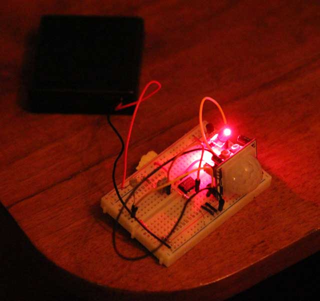
The results of my analog experiment were a success. The laser lights up when it detects movement at night, but doesn’t do anything during the day. And the battery is still going after more than a week of testing. Voltage is holding steady at 4.900v — 1.225v per cell which is about what a NiMH cell measures after a few days of being off the charger, but not yet really depleted. Plenty of charge left!
Designing the circuit
The first part of this was just figuring out what was supposed to be happening. And it’s actually quite simple.
There are 2 states: Daytime and Nighttime.
- During the Daytime, nothing is supposed to happen.
- During the Nighttime, the motion sensor is powered up looking for any movement.
This leads to 2 more (sub)states of Nighttime:
- If Motion, turn on laser
- When motion stops, turn off laser
Redditor /r/doakey selected this Passive Infrared (PIR) motion sensor and it does a great job of sensing motion. It has a sensitivity dial, and a timer dial to state how long to signal after it has detected motion. It also has the option to repeatedly trigger when it senses motion.
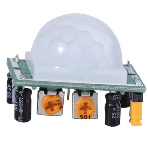
This PIR sensor is reasonably low power (spec sheet says 1.6mA), is fairly cheap (~$1.75 per unit) and takes care of the 2 sub-states at Nighttime. So the hard part of this circuit is mostly about reliably detecting daytime and nighttime.
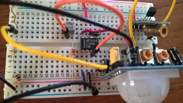
Ok, time to show you the working circuit. It may seem complex, but it’s not too hard to understand. We’re going to work from left-to-right:
–Click on the above image to open an interactive circuit simulation–
(People using the NoScript plugin with their browser may have difficulty opening this simulation.)
The first thing to point out is that +5 volts was chosen to power the circuit. All of the major components (PIR sensor, Laser, etc.) work well on 5v. And four (4) NiMH AA cells in series produce approx 4.8v. The comparator can work well below 5v and the PIR sensor works down to 4.5v and the laser also works pretty well at that level, too. So this was a good choice for batteries.
Stage 1 – The Day / Night sensor
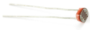
 To detect when it is light and dark, a photocell (also known as a CdS cell) can be used. The photocell changes its resistance as more or less light hits it. Specifically, when bright out, the resistance is low and when dark, the resistance is high.
Since we’re trying to use as little power as possible, the choice came down to using a CdS cell with a high resistance. In this case, the photocell has a range of 500 ohms to 1 Megaohm (1 Million ohms.) In order to create a signal from this photocell, we need to make a “Voltage Divider” out of the cell by placing a resistor next to it.
As mentioned previously, resistors only resist CURRENT flow, but when you have two resistors in series, the middle point between them creates a “Voltage Divider”. The linked Wikipedia entry explains it well.
The CdS photocell is represented in this schematic by a potentiometer with one end not attached and the green arrow. It should probably be right about here on a full-screen web page ======================>
(Apologies to people reading from their phones…)
In this circuit, we use the photo cell and a 33kohm resistor to create the divider. Since the photocell can vary its resistance, the 33k resistor on the bottom can create a maximum of ~4.2v and a minimum of around 0.5v. According to calculations, the circuit on average will draw a mere 60 microAmps (well, a range of 5 – 130 uA, depending on how dark/light it is.) Shown here, the voltage divider creates 1.9v, which is somewhere between daytime and nighttime.
This is stage 1 of the circuit. It signals whether it is daytime (high-ish voltage) or nighttime (low-ish voltage).
But the natural question is: What defines day from night? Where’s the threshold?
Stage 2 – Comparing the Day / Night signal
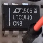
 To resolve this, we move to stage 2 of the circuit where we use a component known as a “comparator”. And it does exactly what it sounds like: it compares an input “signal” voltage to a reference “threshold” voltage.
The comparator is represented by the triangle with the (+) and (-) sign. What’s NOT shown here is that the comparator is powered. Yes, there are actually 2 pins not shown in the schematic that connect the comparator to our +5v and Ground (GND) in order to give it power.
In the schematic, it is *implied* that it is getting power from somewhere. (In our case, +5v and Ground — 0v.) This is an important concept to understand as a comparator only outputs two voltages: the high and low voltages that it is powered by. In our case, since we feed it +5v and GND (0v), it can only output +5v and 0v.
You’re probably nodding by now because you’re realizing that a comparator can create a HIGH and LOW state (like a 1 or a 0 in digital logic.) Cool, right? Although in this case, we’ll be directly driving the next stage (the motion sensor) with the 5 volts that it outputs. But we’ll get to that in a minute…
Another thing that needs to be said about the (+) and (-) of the comparator is that these inputs are NOT positive and negative. The plus (+) symbol represents “non-inverting” input and the minus (-) symbol represents “inverting” input.
So what does this mean?
For what we’re doing here, this is very important. When it is daytime (HIGH voltage) we don’t want anything to happen. When it is nighttime (LOW voltage), we want the magic to happen. This is the exact opposite of the voltage values that we desire. An “inverting” input outputs the opposite value of the threshold while a “non-inverting” input will output a voltage of the same “side” of the threshold.
In other words, with the “inverting” input, if the input value is LOW-ish, the output will be fully HIGH (5v). And if the input value is HIGH-ish, the output will be fully LOW (0v). In constrast, with the “non-inverting” input, if the input voltage value is LOW-ish, the output value will be fully LOW (0v). And vice-versa.
We’ll use some numbers to explain. Let’s assume that our comparator is using +5v and 0v (GND) for power:
If we use a reference voltage of 2.5v and put it on the (-) input, if the signal voltage on the (+) is ABOVE 2.5v, we get a HIGH voltage (5v). If it is below 2.5v, we get a LOW voltage (0v) out. This is known as “non-inverting“.
If we (again) use a reference voltage of 2.5v. This time on the (+) input, if the signal voltage on the (-) is ABOVE 2.5v, we get a LOW voltage (0v). If below 2.5v, we get a HIGH voltage (5v) out. This is known as “inverting“. (The output voltage is on the opposite side of the threshold compared to the input voltage.)
As you can see, the comparator makes strong and clear sense of things (HIGH & LOW) out of things that may be weak and vague (HIGH-ish & LOW-ish)
Since we want LOW (nighttime) to signal HIGH (power to IR sensor), we send our input to the “inverting” input (-) and we apply our reference threshold to the (+) input.
Creating the “reference” (threshold) voltage
 As shown in the schematic, the reference voltage going to the (+) input is a lot like stage 1 where we created a voltage divider, except that we’ve used a potentiometer to create a varying threshold (instead of the photocell.) Specifically, this will allow the user to set a threshold between 1.25v and 3.75v.
Maybe you want the laser to turn on when it is still somewhat light out, say just before dusk. Maybe you only want the laser to turn on when it is very dark. It’s up to you. Just spin the screw on the trim-pot and set the threshold.
Shown at the right as a green arrow, the trim-pot (a type of potentiometer) is set to the middle of its range and is producing a voltage of 2.5v for the comparator to use as a threshold (or “reference”) voltage.
Stage 3 – Detecting motion when it is dark
At this point, we can assume that it is dark out, and stages 1 and 2 have set the comparator such that we’re getting 5 volts from the output pin. This comparator can only supply up to 40mA of current. This is not typically a lot of current, but fortunately for us, our Passive IR (PIR) sensor module only needs a maximum of 1.6mA — this is well within the abilities of the comparator. Good!
The PIR module has its own circuitry with 2 potentiometer dials. One to tweak the motion sensitivity and the other to adjust the “hold time” after it has sensed movement. There isn’t much to explain at this stage as this is a self-contained module. Just fiddle with the dials to get the right sensitivity and a long enough hold time.
Stage 4 – Switching on the laser
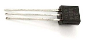
 The PIR module outputs a signal of 3.3v (HIGH) when motion is sensed and 0V (LOW) when nothing is happening. To control power, my preference is normally to use a power MOSFET, but when I started reading up on lasers, I realized that they are “current controlled” devices much like LEDs. So I decided to use a (cheaper) Bipolar Junction Transistor (BJT) in “saturation mode” here.
Like a MOSFET, the BJT in saturation mode acts just like a switch: On or Off. Although, it still left me with an easy option later to limit the current if it was needed. (It wasn’t. The laser module had a current limiting resistor on it already.)
A transistor has 3 pins unlike most components you’ve encountered so far which typically have just 2. The Bipolar Junction Transistor (BJT) has a Collector (C), an Emitter (E), and a Base (B).
A simplistic way of looking at this is that the bulk of the current flows between the Collector (C) and the Emitter (E). And the amount of current flowing between the Base (B) and the Emitter (E) is what controls whether current is allowed to flow between the Collector and the Emitter.
The output from the PIR module connects to the base of the NPN transistor. When the signal goes HIGH (3.3v), the transistor turns ON and allows current to flow from the Collector to the Emitter. When the Signal goes LOW (0v), the transistor turns OFF and current stops flowing.
So we wire the +5v source to the positive input on the laser and we connect the ground pin of the laser to the BJT’s Collector. From there we connect the Emitter pin of the BJT to Ground. Now the BJT directly controls the laser depending on the signal it gets from the PIR module.
It should be noted that the laser should not be placed between the Emitter and Ground because it would prevent the transistor from allowing current to flow and the laser wouldn’t really turn on. In fact, in this schematic, we have a 100 ohm resistor to limit current to about 20mA. Though, as mentioned before, the laser module already had a current limiting resistor on-board, so this 100 ohm resistor is kind of unnecessary, but it certainly doesn’t hurt either.
Measuring the circuit’s current usage
When designing this circuit, it was fairly easy to estimate the power usage based on Ohm’s Law and reading from the spec sheets, but finding out the truth of the matter wouldn’t be possible until building the circuit. The results from my digital multimeter were:
- Daytime, Laser Inactive: ~0.2mA
- Nighttime, Laser Off: ~0.2mA
- Nighttime, Laser On: ~20mA
As you can see, the circuit draws very little current when just sitting around idle. The lion’s share of the current draw is when the laser turns on. Thus if using a four pack of 2000mAh AA Eneloop rechargeable batteries, this circuit should be able to idle for 10,000 hours. That’s over a full year!
Naturally, when the laser is on, it increases the power usage 100x! But when running 24 hours a day, that’s still 4+ days!
What I found interesting was that the current draw between daytime and nighttime didn’t really change. During the day it was 0.19mA and at night is was 0.18mA. Although I was not surprised by the CdS photocell drawing less power at night (resistance goes up when dark), I was surprised at how little power the PIR motion sensor actually used. The spec sheet said 1.6mA, but it turned out to be more like 0.1mA.
What was particularly impressive was how little power the comparator used: 2.4µA (which was right about what the spec sheet said it would draw: 2.1µA)
Yup, 2.4 Micro amps. Considering the comparator is what we are using to replace the Arduino with, well, now you see why the Arduino (which normally uses 45mA per hour) killed /r/doakey’s battery so quickly. The Arduino uses 18,000x more current than the comparator.
Getting current draw even lower
If you read up on Gammon’s Arduino Power usage page, you’ll quickly find that you can get the Arduino down to super lower power usage modes — comparable to what was designed here using analog circuitry.
Although, it should be pointed out that you do lose a fair amount of functionality in some of these low-power Arduino modes. For example, disabling Analog-to-Digital conversion (ADC) saves a good deal of power, but, well, you’ve just disabled ADC which you need for the CdS cell to detect the light levels.
Always up for a little challenge, this led me to thinking how to save more power in the analog circuit:
- Replace the CdS cell, the 100k trim-pot, and the other signal producing resistors and voltage dividers with even higher resistance components. Right now, they’re using far too much current just to produce simple signal voltages for the comparator. The LTC1440 comparator needs almost no current to take proper measurements, so this would be an easy way to save more power. This could save 50µA or so.
- The PIR sensor doesn’t use a lot of current when sitting around. 90µA isn’t that much, but I’m sure a different yet equally effective circuit could be found that uses even less. This could also save 50µA.
- The LTC1440 comparator uses 2µA. I suppose you could find one that uses 200 or even 20 nanoAmps, but it’s probably not worth chasing…
- And then there’s the laser. That’s the 800-lbs gorilla in the room. (Am I mixing metaphors? Meh, who cares…) That said, I don’t think there’s much you can do about this. It draws 15 to 25mA. Maybe there are more efficient lasers. I’m not a laser expert. ¯\_(ツ)_/¯
Let’s review
Stage 1: Use Photocell and resistors to make a voltage divider. Gives a range of 1 to 4 volts as a “signal” of day or night.
Stage 2: Connect day/night “signal” to “inverting” input and set the threshold voltage to the other pin of comparator.
Stage 3: The output of the comparator directly powers the Passive IR (PIR) motion sensor during the night time.
Stage 4: When the PIR sensor detects motion, it sends the signal HIGH (3.3v) to the NPN transistor which turns on the circuit and shines the laser.
And that’s it! 🙂
5 replies on “Bathroom Laser Light project — the analog version”
A phototransistor is a better choice than a cadmium sulfide LDR because its dark current is zero. So you don’t need to make a two legged bridge and differential comparator, while drawing bias current in both legs and in the comparator.
With a phototransistor you only need a single leg (phototransistor + pullup resistor) connected to a single ended logic gate like a 74HC14. You get huge output voltage swing because the phototransistor’s current is an exponential function of illumination. And you get zero bias current too.
How is the threshold for day/night set?
If I wanted to study things related to this, so that I can understand it and design similar things myself, would I search for electrical engineering courses?
Can you share the parts list for this project. Thanks in advance.
Yes, in fact, I can. Turns out I’m building a whole bunch of them now. I’ll post the parts list when I start building them in a few weeks.