While designing a project that required 5v USB power ports from a much higher voltage source (eg. 12v or 24v), it occurred to me that there are circuits already designed to do this. In fact, not only do they exist as low-cost, easy-to-purchase modules, but some of them already have the USB port soldered onto the board.
Four Step-down converters with USB ports were picked out and reviewed in an attempt to find “the best cheap USB switch-mode step-down converter” for 12v power supplies.
How does a Buck (step-down) converter work?
Before getting into the testing, it is probably prudent to cover how a switch-mode step-down converter actually works. While it may seem complex, it’s actually rather simple and is centered upon 1 single component to perform the bulk of the work: The Inductor.
Understanding the Inductor
If you are unfamiliar with what an inductor is, it can be described simply as a wire coated in a non-conductive enamel and then that wire is (typically) wrapped around a metal ring or rod. (The non-conductive coating is to prevent short-circuits from winding the wire around the ring.)
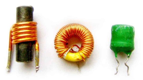
Image credit: Wikipedia page on Inductors
What happens with an inductor is two-fold:
- When current starts passing through the wire running around the ring, an invisible magnetic field is created. The inductor acts like a resistor with an initially high resistance. As the magnetic field continues to grow, the resistance drops toward zero. As long as current is applied to the inductor, the field is maintained.
- The interesting part is when the current is removed from the inductor. The field begins to collapse, the inductor resists this change, and all the energy stored in the magnetic field forces the electrons to begin flowing again, causing a rush (or spike) of current in the wire.
The important thing to understand is that the inductor resists change in current passing through it and it resists by storing that energy in a magnetic field and then later giving up that stored energy when needed.
This is why a switch-mode converter is able to be so efficient compared to converters like linear regulators or voltage dividers which just resist current by converting unneeded energy to waste heat.
Understanding how the Inductor can step-down voltage
Now that one of the basic concepts of an Inductor can be thought of as an energy storage device, let’s consider how we can use this to our advantage. If we rapidly turn on and off the current to the inductor, we can regulate how much energy we want to put into the inductor and depending on how long things are on versus off we can effectively step-down the voltage to a desired amount.
To do this, we need a very fast electrical switch (transistor) known as a MOSFET.
Looking at the circuit diagram above, we can see that we have +12 volts connected to the MOSFET (represented here as an opening and closing switch) controlled by a square-wave clock (labeled CLK) and immediately connected to the Inductor (marked as 1H — 1 full Henry is actually overly large — this size was selected purely for the simulation).
- When the clock (CLK) switches the MOSFET on, it charges up the inductor (storing energy) while simultaneously dropping the voltage flowing through the wire. As the inductor continues to charge, the resistance continues to drop and the voltage continues to rise again.
- When the clock (CLK) switches the MOSFET off, the inductor’s magnetic field collapses. At this point, the inductor becomes negatively charged and draws current up from ground through the diode keeping the current flowing. (The 100µF capacitor smooths out any ripples in the output.)
As seen in this simulation, the 12v input is dropped to around 5v volts output.
Here’s the take home: The frequency and duration (duty-cycle) of switching on / off combined with the size of the inductor form the basics of how a Step-Down converter works.
An advanced step-down converter has a complex IC/chip which regulates the larger circuit using feedback in an intelligent manner such that it can constantly adapt the switching frequency and duty-cycle to maintain a steady voltage on output regardless of changing load or input voltage.
Examining the buck (step-down) converters
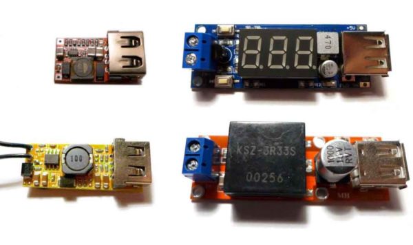
For this review, four (4) different cheap Buck (step-down) modules were selected based on what looked like good design and had a USB port already built-in. Two different modules were from Drok, one from SMAKN, and another branded as Ailavi.
Modern step-down converters have a few components to pay attention to:
- The switch-mode regulating chip
- The inductor
- The smoothing capacitor(s)
1) The switch-mode regulating chip
If the inductor is the brawn, then the switch-mode regulating chip is the brains of this whole operation.
Examining the 4 step-down converters revealed that there were 3 different regulating chips in play. Here’s a quick table showing the module and the regulating chip.
| Drok w/ LED | Drok | Smakn | Ailavi |
 |
 |
 |
 |
 |
 |
|
 |
| XL1509 | MP2307 | MP2307 | MP2315 |
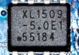
The XL1509 chip is designed and manufactured by a Chinese company called XLSemi and has a relatively low fixed switching frequency of 150kHz. It doesn’t use MOSFET transistors to handle the high-side switching, but Bipolar Junction Transistors (BJT) instead.
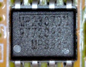
The MP2307 chip is found on two different modules: one of the Drok modules and also the Smakn module. It is designed and manufactured by a California company called Monolithic Power Systems (MPS). The MP2307 chip was first manufacturer in 2008, has a 340kHz fixed switching frequency, and MOSFETs with high and low side switching resistance of 100 milli-Ohms. (desirable!)
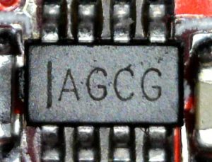
The MP2315 (also by MPS) was first manufactured in 2014, has a 500kHz fixed switching frequency, and MOSFETs with 90 milli-Ohm (high side) and 40 milli-Ohm (low side) resistance. (even more desirable!)
So what do these specs mean?
The switching frequency is the rate which the MOSFET is turned on and off. As switching frequency goes up, efficiency goes down. It would be easy to think that the XL1509 with its comparatively low switching frequency would be the most efficient, but that’s not the whole story. If you read the spec sheets on each chip, it turns out the XL1509 is the least efficient of the bunch.
Why is the XL1509 less efficient despite having a lower switching frequency?
Well, a 150kHz switching regulator chip is typically only about 3 to 5 percentage points more efficient than a 500kHz chip (all else being equal.) The converters using the MP2307 and MP2315 chips have MOSFETs with low Rds(on) resistances of under 100 milli-Ohms. Compared to the XL1509, which uses BJT transistors for switching, the MP2307 and MP2315 chips are able to switch (or pass) power more efficiently despite having a higher frequency.
What’s the significance of the Rds(on) resistance?
The resistance of the circuit when a MOSFET is switched on contributes to the power loss of the conversion: The lower the Rds(on) resistance, the better. The MP2307 has 100 milli-Ohms for both high and low side switching. The MP2315 is a bit better having 90 milli-Ohms and 40 milli-Ohms for high and low side switching, respectively. This averages out to about 65 milli-Ohms (given a duty cycle of 50%) which is a good deal lower than 100 milli-Ohms.
The XL1509? Well, it doesn’t use MOSFET transistors, but uses BJT transistors instead. BJTs tend to be less efficient for power switching than MOSFETs. On top of this, the XL1509 doesn’t have low side switching. The step-down circuit relies on a diode to passively perform the role of low side switching which makes the conversion less efficient than one that has some sort of transistor for low side switching.
2) The inductor
The choice of the inductor (more or less) goes hand-in-hand with the frequency of the switching regulator chip. Higher frequencies require inductors with smaller values. For example, the one Drok module has a 150kHz switching frequency and a 47µH inductor. The tiny Ailavi module has a 500kHz switching frequency and a small 4.7µH inductor.
Since the 4.7µH inductor has a lower value, it has less energy storage which is ideal for the higher switching frequency. But the real advantages are that the entire module can be built to be smaller and cost less — both serious advantages!
Ripple
If you’re unfamiliar with the term “ripple” in terms of electronics, it can be summarized as “unwanted variation” in DC current. A battery outputs a steady voltage with no ripple, but a DC-to-DC or AC-to-DC conversion will always have a little ripple in the output voltage. A tiny amount of ripple is fine, but significant ripple can cause instability in some DC circuits. Computers, radios, and cellphones are often susceptible to ripple depending upon how bad it is and if the switching frequency is close to the operating frequency of said device.
3) The capacitor
Fortunately, large capacitors can smooth out ripple. Higher switching frequencies coupled with smaller inductors can also produce smoother ripple.
Looking at the four modules in this review we can see good examples of this. The Smakn module has a giant 1000µF capacitor. This should be able to smooth out any ripple well.
The Ailavi module has the highest switching frequency of the bunch (and also the smallest value inductor as well.) As such, it should have minimal ripple as well. Since it already has minimal ripple, much smaller capacitors can be used to smooth out any ripple remaining.
A quick overview of the 4 modules
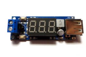
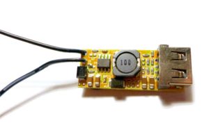
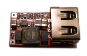
The Drok with LED display module
The Drok module with the LED display is the first module in this review. It features a + and – screw terminal for easy wiring and 2 buttons to control the operation of the unit. The top button turns the display on and off. The button button enables and disables power output. The LED display shows the input voltage. It has a nice 47µF cap on the output rail and separate solder points if the user desires to connect a wire directly to the outputs instead of thru the USB port.
The Drok with no display
The Drok module with no display is much smaller than its big brother. There’s a lot less to this unit in terms of features. Strangely, the design put the + and – rails right next to each other (as shown in the picture.) This seems kind of unsafe in that it wouldn’t take much to a short circuit. Aside from that it also has some small ceramic capacitors on the input and output rails. Overall it seems well designed.
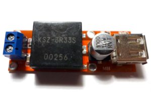
The SMAKN module
The SMAKN module is a bit of a mystery as almost the entire module is encased in a plastic enclosure. It has screw terminals like the larger Drok for easy connecting. It also has separate input and output terminals for soldering. It also has a rather large 1000µF capacitor on the output rail.
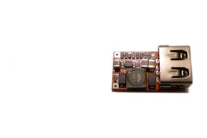
The Ailavi module
Yup, it’s really that small relative to the other 3 modules. The + and – input rails are unlabeled for some unknown reason. Fortunately, the module has a reverse polarity protection diode in case you accidentally wire it up backwards. It also has 1 ceramic capacitor on the input rail and 2 on the output rail and an over voltage protection clamp. And an LED to indicate power to the circuit. (A nice touch.)
Testing the step-down converter modules
Voltage and voltage droop
Since all four of the step-down converters are designed to power/charge USB devices, the first test was to check the voltage out. Since they’re USB, they’re supposed to be +5v (plus or minus 5%), according to spec. Additionally, many power supplies will have their voltage droop when under load.
| No Load | Under Load (1A) | |
| Voltage | Voltage | |
| Drok (w/ LED) | 5.00 | 4.93 |
| Drok | 5.11 | 5.03 |
| SMAKN | 5.35 | 5.33 |
| Ailavi | 5.15 | 5.03 |
As can be seen in the above table, the Drok with the LED display outputs exactly 5.00v and droops down to 4.93v volts under a 1 amp load which is well within USB specifications.
The other Drok (without the LED display) and the Ailavi both output 5.1 volts (very common for USB power supplies) and droop to around 5.03 volts under a 1 amp load. This is an ideal design as the power supply should stay within USB spec under all load conditions — even a 2 or 3 amp load.
The SMAKN module outputs 5.35 volts. This is technically a problem since USB spec allows for the voltage range to be between +4.75 and +5.25 volts. The SMAKN module is exceeding spec by 0.10 volts. Even under a 1 amp load, the supply only drops to 5.33v.
Realistically, this is probably not a problem for most devices. Many smartphones have their own DC-DC conversion circuits on-board which can *probably* handle 5.35 volts just fine. All devices on-hand were able to hand this voltage without any noticeable problem. That said, over-volting is more likely to damage a device over time than under-volting it.
Efficiency
Reading the spec sheets for each chip suggested that the XL1509 should obtain around 80% efficiency, while the MP2307 should come close to 90% and the MP2315 should hit 95% efficiency. Testing these claims was the next order of business.
To complete this test, a digital ammeter was placed in-line with the input to measure current draw. Then a USB digital ammeter was placed on the output port to measure how much was being drawn out.
(Power out ÷ Power in) × 100 = Efficiency %
For this test, various common USB loads were tried with a 12v source:
- 250mA (end of charge)
- 500mA (slow charge)
- 1000mA (fast charge)
- 1500mA (faster charge)
| Current Draw | Drok w/ LED | Drok | Smakn | Ailavi |
|
|
|
|
|
| 250mA | 61.7% | 80.0% | 64.9% | 81.1% |
| 500mA | 69.9% | 83.8% | 74.5% | 85.2% |
| 1000mA | 74.6% | 86.8% | 83.4% | 87.3% |
| 1500mA | 71.8% | 86.7% | 85.4% | 86.5% |
The Drok with the LED display is the least efficient measuring between 60 and 75% depending on load. It’s most efficient (75%) at 1000mA load. Not very good.
The Smakn starts out poorly (65% efficiency) under light load, but manages to hit 85% efficiency under a 1500mA load.
And the Drok with no display and the Ailavi are both highly efficient starting at ~80/81% efficiency under light load (250mA) and hitting 86/87% efficiency under heavier load (1500mA).
The Ailavi with its slightly newer chip edges out the Drok by a consistent 1 to 2 percent, except at 1500mA where they seem to be about the same.
USB charge rate
Just because a step-down regulator can technically supply enough current, doesn’t mean that your phone or device will actually take that much. As it turns out, there is signalling on the USB data lines to indicate how much current a device is allowed to take. Unfortunately, this isn’t consistent across all devices. Apple has 3 different signatures, Samsung has their own signature, and then there is the USB standard for indicating whether a device is allowed to fast charge or not.
The signaling table is as follows:
| Max. current |
D+ | D- | |
| USB slow charge | 500mA | floating | floating |
| USB fast charge | 1000mA | D+ line and D- line shorted together | |
| Apple Slow | 500mA | 2.0v | 2.0v |
| Apple iPhone Fast | 1000mA | 2.8v | 2.0v |
| Apple iPad Fast | 2100mA | 2.0v | 2.8v |
| Samsung Fast | 1000 or 1500mA | 1.2v | 1.2v |
Source: APC Mag: Android USB charging secrets
As shown, Apple uses three permutations of 2.8v and 2.0 on the D+ and D- data lines, while Samsung sets both data lines to ~1.2v, and the USB standard just shorts the two lines together to indicate high-speed charging. Floating (un-grounded) data lines seem to be universally understood as slow speed (500mA) charging.
Testing the USB charge rate
And sure enough, each step-down conversion module has its own special way of signaling on the data line. And interestingly enough, the devices that we used in testing sometimes chose the highest current rate that they could charge at and other times, they chose lower current rates than what was available. Here is a table of the actual measurements of the data line voltages:
| D+ rail | D- rail | |
| Drok (w/ LED) | floating | floating |
| Drok | 2.74 | 2.05 |
| Ailavi | 2.8 | 2.8 |
| SMAKN | 2.99 | floating |
The Drok with LED readout seems to indicate slow charging. The Drok with no display indicates Apple Fast charging, while the Ailavi sets both lines to 2.8 which I’ve read can mean 2400mA charging. The Smakn seems confused as the D+ rail is 3v and the D- rail appears to be floating.
When attached to devices different things actually happened, as summarized in this table:
| Current Draw (mA) | Android | iPhone | Anker battery pack |
| Drok (w/ LED) | 1000 | 1000 | 1000 |
| Drok | 500 | 1000 | 2000 |
| Ailavi | 1500 | 1000 | 2000 |
| SMAKN | 500 | 0 | 2000 |
The Winner
With testing concluded, it was easy to see that there was one clear winner:
The Ailavi DC-DC Step-Down Buck Converter 5V/3A USB Output Module ($7.25)
The Ailavi provides:
- Ideal voltage (~5.05v) even under 1.5 amp load
- Supports continuous current draw up to 2.1 amps (3.0 amps max with heatsink.)
- Properly signals maximum charge rate to Android, iPhone, and non-phone devices
- Fairly wide input range: 6v – 24v
- The most efficient (85 – 87%) @ 12v input
- The smallest of them all
The Runner-ups
The Drok without the display was a competent competitor being nearly as small and nearly as efficient (84 – 86%). Unfortunately, it only seemed to signal maximum charge rate to Apple devices properly and it costs $8.25 ($1 more than the Ailavi).
The Drok with the LED input voltage display was less efficient (70 – 75%) and larger than the rest, but had the widest input voltage range of 4.5v to 40v. It also seemed to signal 1000mA (fast) charge rate to all devices and usually sells for $7.00.
The Smakn module is a funny one because it uses the same chip as the smaller Drok module. And yet, it doesn’t perform as well at lower loads (65 to 75% efficiency). But at higher loads, it approaches 85% efficiency. Unfortunately, it doesn’t signal to devices properly, so either devices like Android will charge slowly or like iPhone not at all. It also plays a little “fast and loose” with the voltage kicking it up to 5.35v. While this is probably okay in practice, it’s technically outside of USB spec. It also sells for around $7.00.
7 replies on “A review of four Switch-mode Buck (Step-down) converters with USB ports”
Thanks, this is an excellent useful comparison. Based on this I bought a MP2315 based module that looks identical to the Ailavi, but badged QSKJ (to step down a 24v supply from a boiler I am building a esp8266 WiFi heating control for :))
Thank you for the explanation. The provided operational insight allows for better understanding and conscious choice when picking components. Bookmarked!
I was after a buck converter integrated to multiple USB outputs for USB charging hub design/project when I stumbled upon this nice comparison. While I welcome any suggestion towards my initial goal, this is a good review and I recommend for DIY people. Great work.
So basically the MP2315 is the outright winner if you pull that input protection diode.
Yeah, probably! Can’t imagine it would be too hard to pop that diode off either…
Thank you! I’m buying the “FINE” to replace a mechanical regulator for my fuel gauge. 🙂
Could you suggest a setup specific for a raspberry pi 4, as follows: continuous charging of a 100Ah deep cycle battery while simultaneously sustaining the draw of a Raspberry Pi. If this is possible, without additional switches, and some sensors that provide a LED display of A drawn, charging information. The goal: an always on situation where a 24h+ grid failure, spikes and brownouts would be neutered. Where the Pi(5V -3A) has a reliable functioning mode.